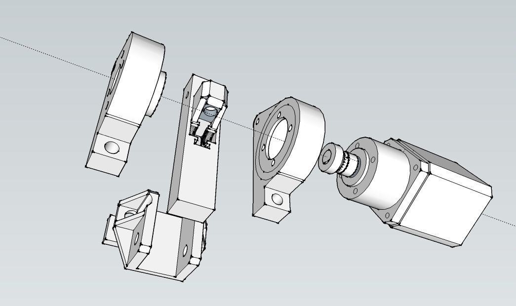
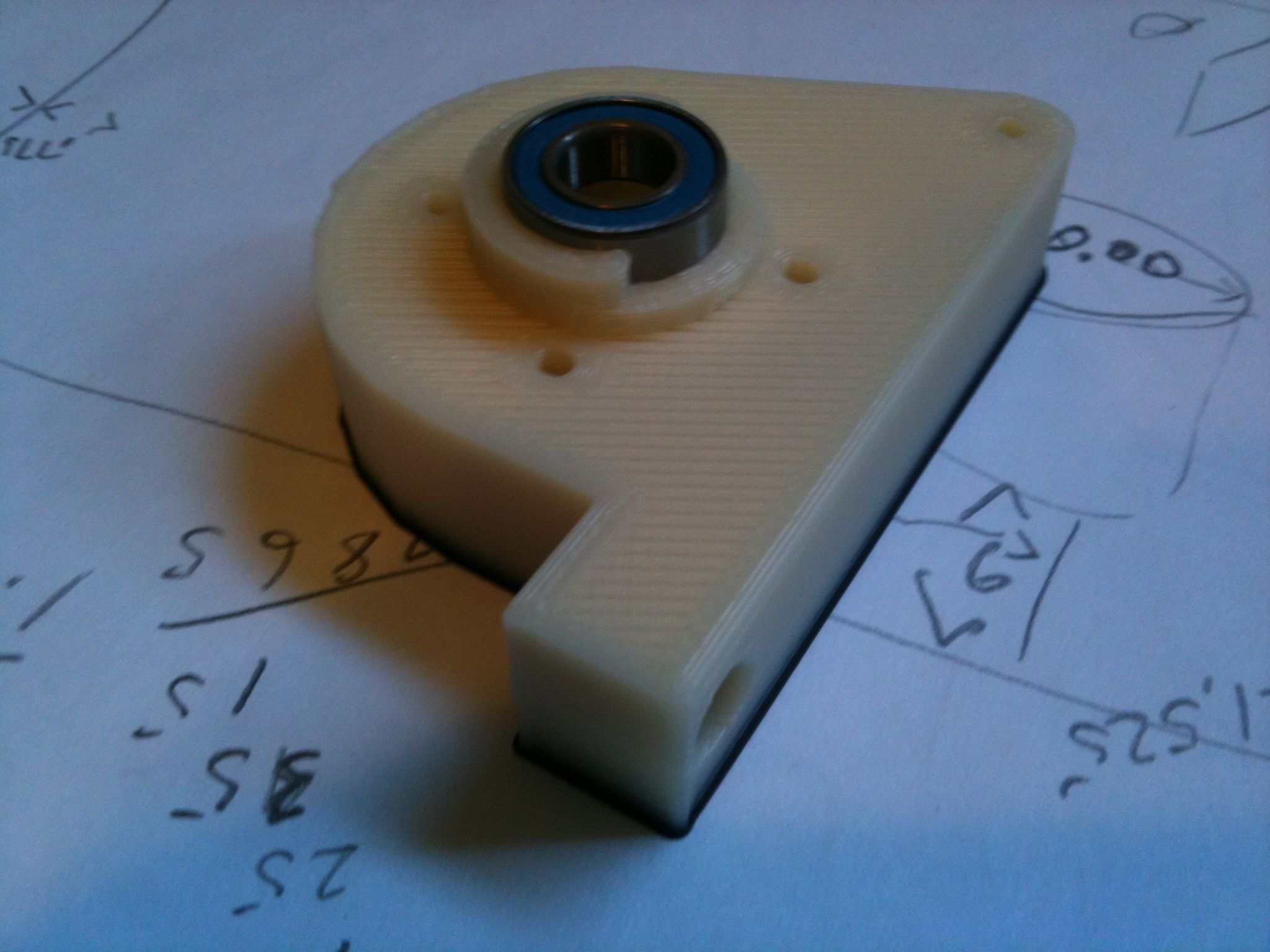
This is an extruder designed to be used with 3mm filament in conjunction with a Bowden tube between the extruder and the hot end, to help reduce the mas of the moving print head.
The design objectives were to provide for a way to reduce the lateral loads on the gear reduction output shaft, securely mount the tube to the extruder (and the tube to hot end), expose the hobbed gear as much as possible for inspection and cleaning, keep filament centered as it enters tube and finally, be made from easily accessible parts.
It uses a 5.2 to 1 gear reduction nema 17 stepper motor, a modified compression fitting to solidly hold the PTFE tube in place and Airtripper’s fuel line based tensioner. It mounts on a 20x20mm aluminum extrusion.
This 0.1 version has been working on a delta type printer for approximately 4 months now and has been solid so far. Retraction settings have been the most challenging obstacle so far, it seems as if every brand of filament act slightly differently.
Future modifications: eliminating the compression fitting and directly threading the PTFE tube into the filament guide would be first in line. A fast release would be handy. Could be much more compact. Integral filament wiper…
If you choose to build one here’s what you’ll need.
The STLs are here: http://www.thingiverse.com/thing:142977
Vitamins:
1/4″ compression x 1/8″ pipe fitting A Watts model with a UPC of 042805445372 works fine
2 – 8 x 16 x 5 ball bearings. Traxxas PN #5118 is a package of 2
2 – 4 x 60mm bolts for tensioner
1 – 5 x 60mm bolt for motor mount pivot
1 – 3 x 40 flathead screw to stabilize idler bearing side to motor side
3 – 3 x 8mm flathead screws to fix motor to extruder
2 – 5 x 20mm flathead screws to fix extruder to printer
1-14mm length of 8mm rod for idler bearing
50mm section of 1/4″ inside diameter high pressure fuel line for the tensioner
You will also need a few tools:
Drill press, while not mandatory, makes the job easier. Substitute a drill motor and steady hands if you need to.
1/4″ x 20 tap & appropriate drill bit (wikipedia sizing chart calls for an #7 sized bit, 13/64″ or even 7/32″ will work)
1/4: x 20 die & 1/8″ drill bit (the drill bit is used to keep the PTFE tubing from collapsing while cutting the threads)
1/8″ pipe tap & 11/32″ drill bit (the hole on the stl could also be properly sized prior to printing)
Steps:
Once the parts are printed (ABS, 50% infill) and vitamins sourced,
1. Drill and tap extruder body


2. Insert the idler bearing and shaft into extruder body (not shown).
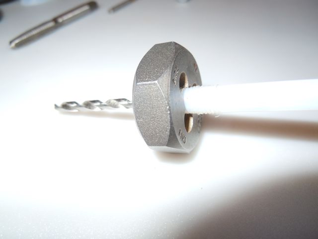
3. Drill and tap the compression fitting with a 1/4″ tap. This gives a significantly stronger grip on the PTFE tube than compression alone.
A wooden block drilled…

…and tapped to hold the fitting while machining helps keep the work in alignment.

Use an end wrench to hold the fitting while machining or the fitting may strip out the wood block.

Tap the inside of the compression fitting all the way through with the 1/4″ x 20 tap (not shown).
4. Thread the compression fitting into the extruder body and tighten. Be careful not to tighten too much or the extruder body may split.
5. Tap the outside of the PTFE tube.
Slide the 1/8″ drill bit up into the inside of the tube to prevent collapse while tapping.
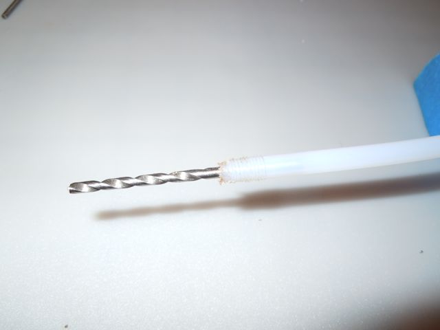
Tap the outside of the tube with the 1/4″ x 20 die approximately 17mm, enough so that the end of the tube can be threaded through the compression body, to near the hobb when assembled.
6. Slide the compression nut and collar up the PTFE tube (not shown).
7. Thread the tube into the extruder assembly until the tube is close to the hobb.
Tighten the compression nut taking care to not over tighten which could cause ID of the tube to shrink and cause drag on the filament.
8. Mount the drive side to the motor. A bit of counter sinking of the screw holes may be helpful.
9. Press the idler bearing (one of the Traxxas bearings) into the extruder’s idler side.
10. Following the notes in the vitamins section above, use the various fasteners to assemble the extruder.
You’ll need to drill two holes through the sides of the
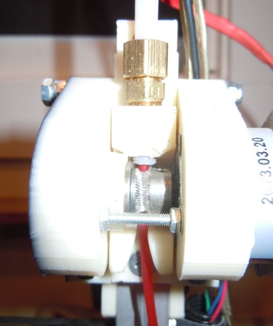
The extruder should now be assembled, ready for loading filament and adjusting. As seen in the image below, the tensioner

The version in the photos is mounted to a short piece of 20mm x 20mm aluminum extrusion mounted to a spool holder.

If there are questions please post a comment and I will do my best to help.
Hello,
I love it! I am getting ready to move to a Bowden design to have dual extruders on my MendelMax 1.5. This might seem like a sill question but what is the silver gear assembly that is directly attached to the stepper motor? I would assume that this is the gear reduction, but where can I find this to buy?
Thank you very much!
Hello,
Found it on ebay I think, is this the correct one?
http://www.ebay.com/itm/Geared-Stepper-Motor-Kysan-1040221-17HG-B1-5-2-750C-Reprap-3D-Printer-Extruder-/290970767826?pt=LH_DefaultDomain_0&hash=item43bf3591d2
Also do you use a standard extruder gear, because I can not find clear reference as to shaft diameter?
Thank you
If I’m doing the math correctly, the one listed here has 20+Kg/cm of torque for $34. Not a brand name like Kysan but I’ve been happy with my Chinese version so far…
The shaft is 8mm. Trinity labs has them here http://trinitylabs.com/products/hobbed-pulley
I got that one from China but can’t find the receipt so don’t have the address. However they are available here http://www.stepperonline.com/gear-51-planetary-gearbox-for-nema-17-geared-stepper-motor-p-40.html for about the same price.
[…] If you want some help along the way there are instructions at http://thefabfor.com/yet-another-bowden-extruder/. […]