A quadrature encoder is often used to calculate distance and direction. There are some good explanations here and here regarding their operation. This page describes a hack that adds a set of 3D printed quadrature encoders to a pair of Power Wheels gearboxes. (I believe these gearboxes are referred to as the Power Wheels #7 series. They came out of a Power Wheels Jeep.) While these gearboxes could be used in a variety of applications they were modified specifically for use on an open source differential drive robot. Consider this design as a work in progress. I hope this is just a jumping off point for further refinements from others. Here are the steps taken to prepare the gearbox and gear, assembly and mounting of the 3D printed parts. Download the files from Thingiverse and print out the parts as seen in the following image. Note: the part in the lower left of the image has had a half round section cut away from it. The cut out is not necessary for this version. 
The parts in the left hand column of the image are jigs for modifications to the gearbox housing and one of the gears. In addition to the printed parts 4 sets of Infrared Emitter and detector pairs will be needed along with 8 2-pole terminal blocks, both available from Radio Shack. 1. Start by cleaning the outside of the gearboxes to prevent dust and dirt from contaminating the gearbox internals.

2. Disassemble the gearboxes by removing the two screws (in the upper left of the image above) that hold the motor in place, pull the motor out and set aside.
3. Remove the 4 screws as seen in the image above (they are the 4 counter sunk screws).

4. Next, while keeping the side with the large white output shaft facing up (to allow the gears to remain on their shafts), release the 4 locking tabs like the one in the above picture and separate the gearbox sides.

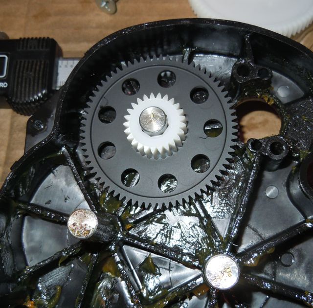
5. Once the case halves are split, slide the largest gear off and what remains will be similar to the image above. The gear on the far left is the one that will be modified so remove it from the housing and wipe it clean. You’ll need to remove all of the gears to remove the one on the far left.

6. Next, gather the blue shim, the gear to be modified, and the red drilling index. Stack them in that order and screw them down to a piece of scrap material as seen in the next image. If you have a spare gear as seen in the image below also attach it to the board as shown. If not, no worries, it’s just a bit of added stability. If the red jig printed well it should form a slight press fit to the gear, no slop. The blue shim will get destroyed when drilling, it’s just there to allow for clean holes to be created in the gear.

7. Carefully drill out each of the 9 holes with a 9/32ths inch drill (or a 7mm drill if using metric tools). A drill press is a great way to ensure the holes are straight but it can be done with a hand drill if careful.

8. Tape off the larger teeth and paint the gear to ensure that it is opaque. The image above shows the gear after priming, before a final coat of flat black. The paint ensures that no light will pass through the gear, creating a high differential between high and low states. The gear is now complete.

9. Move on to modifying the housing by reassembling (without any of the gears) the two halves of the gearbox. Then fit the jig to the housing as seen in the image above. The jig should fit snugly over the two raised pins (one half round and the other round). Drill out the smaller holes with a 1/8th inch drill, all the way through both halves of the housing being careful to let the drill follow the alignment of the jig. Once again, a drill press simplifies this process but isn’t absolutely necessary. Next drill out the larger holes with the 9/32nd inch bit or a slightly larger one, the smaller holes will act as the alignment mechanism once final assembly is done. Be sure to clear out any drill chips that might remain inside the housing.

10. To complete the next step will require a bit of soldering. Insert the emitters and receivers in their respective sockets and, while observing which lead is which, cut to approximately the length the leads will need to be when soldered to the terminals. If you are unsure about how they should be wired Matt S. wrote up a quick test in the customer comments section of the RadioShack.com site where the emitter detector pairs are available.

In this iteration of the encoder each side is populated with one emitter and one receiver with the opposite configuration for the other side. You should end up with one of each for each gearbox being converted.

Remove the emitters and receivers from the body. Solder them to the terminal blocks as in the image above, paying attention to the proper orientation. Insert them into the bodies and secure them in place. The emitters and receivers are held in place with small pieces of foam packing (the packing used in this instance is the type often used to protect ICs during shipping but almost anything flexible will work).


Once the emitters and receivers are in their correct locations and they are held in place, assemble the housings as illustrated above. Use two small flat head screws to secure them together. Take time to indicate what the electrical connections are when putting them together, you’ll be glad you did when it comes time to make the connections. Part “C” has small windows in it to allow for marking the connections.

Using two more small screws, attach each encoder assembly to the gearbox through the previously drilled holes, one on either gearbox housing half. The emitters and receivers should align with the larger holes drilled in the housing. Take a few moments to clear any plastic chips that may have contaminated the inside of the gearboxes during the drilling process. Also, make sure and lubricate the shafts the gears ride on as well as the gear that has been drilled out.
Starting with the modified gear, reassemble the gearboxes. Be sure to lube the shafts and the gears as they go back together, being careful to avoid plugging up the newly created marker holes in the gear. Snap the two gearbox halves together and refasten them with the original four screws. That completes the mechanical modification.
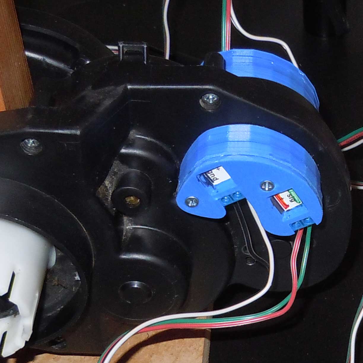
When complete they should look something like the image above. These encoders have been read by an Arduino Duemillanova directly as well as through an LSI computer Systems LS7084 Quadrature Clock Converter and by an Arduino Mega 2560 through Robogaia’s Arduino Two Axis Encoder Counter Mega Shield Version2. The latter configuration is being used on this open source robot running Robot Operation System’s ROS Arduino Bridge package. Testing is still in the alpha stages but results appear promising with a reliable 1228 ticks per drive wheel revolution. Mathematically there are 1228.2912 ticks per revolution but the diameter of the wheel won’t be that accurate so 1228 is OK to use. If further information is desired regarding these configurations please enquire via comments.
[…] These additions to a Power Wheels gearbox along with some open source software and an Arduino allow for sensing how far the gearbox has traveled and in what direction. It counts ~1228 “clicks” per revolution of the output shaft. For Sketchup files or .stls go here. For instructions on how to proceed with the modification click here. […]